
When you’re spending as much time in SOLIDWORKS as we all are, you know how important precision is. In this ecosystem, every dimension matters, making the selection of the correct unit system in SOLIDWORKS crucial.
Making a conscious choice for your unit system in the beginning ensures accuracy, facilitates collaboration, adheres to industry standards, and optimizes designs for manufacturing.
In this article, we’ll explore the practical considerations for choosing the right unit system in SOLIDWORKS, empowering you to make informed decisions that enhance your design process.
Considerations for Choosing the Right Unit System
- Industry standards: Industry standards vary across sectors. For instance, metric units are common in automotive and aerospace industries, while imperial units are prevalent in construction and woodworking.
- Collaboration: Alignment with collaborators is extremely important to prevent errors and confusion during design exchange. Agreeing on a standard unit system enhances communication and workflow efficiency.
- Material Specifications: Materials often have specific measurement standards. Selecting a unit system that aligns with these standards ensures accurate representations and simulations of components and assemblies.
- Manufacturing Processes: Different manufacturing processes may favor specific unit systems. Aligning design specifications with manufacturing requirements streamlines production and assembly processes for enhanced efficiency and accuracy.
Available Unit Systems in SOLIDWORKS
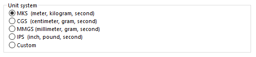
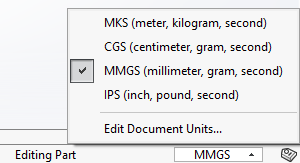
SOLIDWORKS allows users the flexibility to choose between a few standard unit system options as well as “Custom” options where you can mix and match your units. In the image below, you can see these five different options: MKS, CGS, MMGS, IPS and Custom. This versatility caters to diverse industry requirements and global standards.
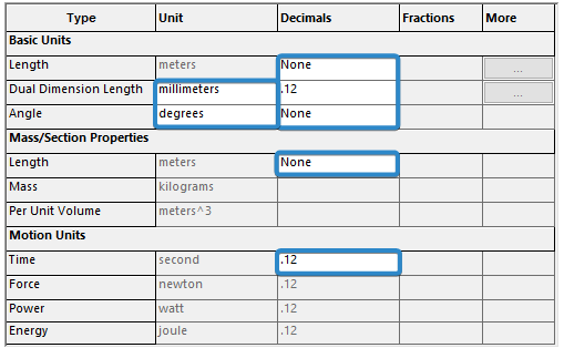
Each one of the default unit system options has items you can modify and some you cannot. Here is an example of what you can and cannot change within the MKS unit system:
Generally, the options you can change are going to be the same in each of the other unit systems.
Some of the main items to consider changing are:
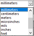
Dual Dimensions Length
- This option allows you to display a second unit dimension of your choice.
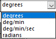
Angle
- You will be able to switch between displaying angles as Degrees or Radians only.
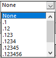
Decimals
- These dropdowns allow you to choose to display results between 2 and 8 decimal places.
- Alternatively, you can choose to display no decimals by selecting ‘None’ from the dropdown.
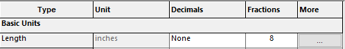
Fractions
- If you switch over to IPS, you’ll also have the option to set the display units in fractions. You can select an integer for the denominator between 2 and 256. This option is only available for inches, mills, micro inches, or feet and inches.
- We’ve changed the Fraction to show all dimensions for Basic Units Length as 1/8” precision.
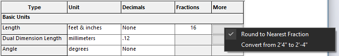
More
- There are two options available to you within the ‘More’ column.
- Round to nearest Fraction: This option appears when you apply fractional precision.
- Convert from 2’4” to 2’-4”: This option appears when you are displaying dimensions in Feet & Inches at the same time.
These are the five columns that will assist in setting the appropriate dimensions for the three different measurement categories.
The categories that you can change units for are:
- Basic Units: Displays document-level dimension units like Length, Dual Dimension Length, and Angle.
- Mass/Section Properties: Displays the length, mass, and density characteristics of your document. These attributes are visible within the Mass Properties or Section Properties PropertyManager.
- Motion Units: Displays document-level units for time, force, power, and energy for motion study results and features.

While SOLIDWORKS allows seamless switching between unit systems, it’s crucial to select the appropriate one from the start. By understanding the available unit systems in SOLIDWORKS, users can lay a solid foundation for precise and efficient design workflows.
Steps to Choose the Right Unit System in SOLIDWORKS when Starting a New Project
When you start a new project, you can choose which unit system you’d like to design in. Some companies or individuals decide to create specific unit templates their users can choose from. If that’s not the case for you, follow these steps to get your project off to the right start.
Step 1: Select ‘New’.

Step 2: Choose ‘Part’.
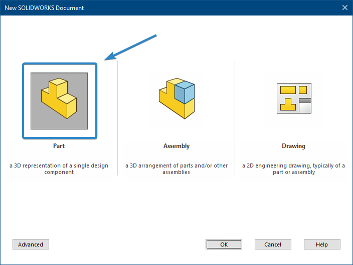
Step 3: Navigate to the bottom right of your new part window to see which unit system the new part was created in.
![]()
Step 4: Choose which unit system you prefer.
Step 5: Save.
Be aware that this change is only for this document. If you start a new part using the same template, you will have to make this change again. It’s best to create a Template for this unit system if you plan to reuse it over and over.
Check Existing Designs
Sometimes you find yourself modeling a part for a project that already has a unit system preference. It’s important to review the unit system used in the existing project to maintain consistency.
- Step 1: Open a component from the reviewed project.
- Step 2: Navigate to the bottom right of the open component window to see which unit system the component was designed in.
- Step 3: Start a new component of your own.
- Step 4: Ensure the same Unit System is selected in the new component.
If you happen to run into a situation where the reviewed component is listed as ‘Custom’ it won’t be as easy as selecting ‘Custom’ and moving on. When this happens, you’ll need to go a few additional steps further to ensure your units matched the reviewed components units.
Customizing the Unit System
The last item is the ability to completely customize your unit system. You have the choice to modify your unit system to show a mix between imperial and metric and you can even go as far as displaying dimensions as precise fractions.
Step 1: Navigate to the bottom right corner>select the units>click ‘Edit Document Units’.
Step 2: Select ‘Custom’. Notice how many of the cells in the Units dialog open. Each one of these individual boxes can be modified to display appropriate units per application.
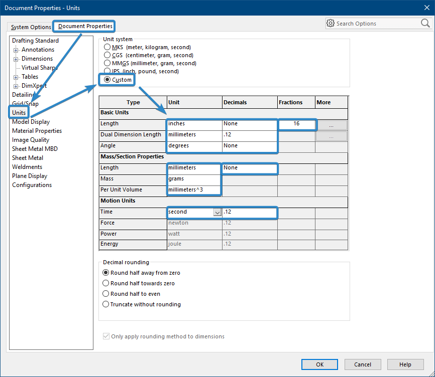
Note: As discussed in the ‘Check Existing Designs’ section of the article, here is where you’d go to examine the reviewed component. Best practice would be to completely copy the unit system of the reviewed component to your new component.
Step 3: Modify. Select any of the available options within the ‘Custom’ unit system to make necessary changes.
Step 4: Accept the changes you’ve made to the documents units by clicking ‘OK’.
Unit Systems in SOLIDWORKS
Picking an appropriate unit system in SOLIDWORKS is very important. Users can make better design choices by thinking about things like industry standards, the need to work as a team, material requirements, and the manufacturing processes. SOLIDWORKS gives users the freedom to ensure that units fit the needs of their projects. This creates a solid base for accurate and efficient workflows.
If you’d like to learn more about creating templates that will have all the unit settings saved so your users don’t have to make any changes, see the Creating a SOLIDWORKS Part/Assembly Template lesson on SolidProfessor. For more questions about Choosing the Right Unit System in SOLIDWORKS, get in touch with Hawk Ridge Systems.