
Taking advantage of symmetry is a great way to improve the efficiency of a
simulation study. Complex studies can take a significant amount of time to
solve. Using a coarse mesh, simplifying geometry, or idealizing boundary
conditions can speed up an analysis, but come at the cost of reduced realism
and accuracy. Unlike these methods, taking advantage of symmetry allows for
results to be calculated in less time without sacrificing accuracy.
I’m going to split this discussion into 3 parts:
-
Using symmetry – when to use symmetry, applying symmetry restraints, viewing
results -
Special symmetry cases
– non-orthogonal symmetry, symmetry for shell elements -
Extreme symmetry
– 2D simplification
So when can we use symmetry? Of course, the geometry has to be symmetrical.
It’s necessary for the boundary conditions (fixtures and loads) to be
symmetrical as well.
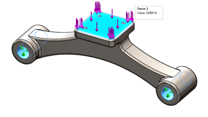
The bracket shown is symmetrical and is loaded symmetrically with fixed hinge
restraints on each side and a load of 32,000 N on the center face. This
analysis is a perfect candidate for simplification with symmetry, so let’s cut
it in half.
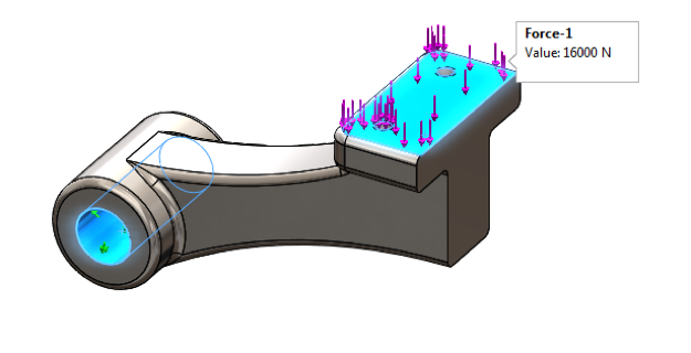
Editing the model is as easy as creating a cut feature and I like to keep
things organized by using a separate configuration. The setup for the new
study is a bit different. We now only have a single fixed hinge restraint and
the applied force is 16,000 N (half of the full load).
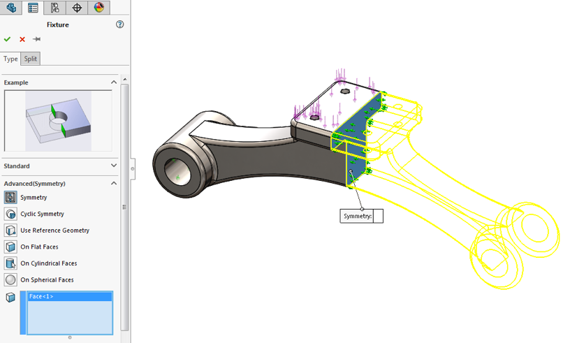
A symmetry restraint also needs to be applied to the cut face on the symmetry
plane. Symmetry can be found under the advanced fixture types. This restrains
the selected face to the symmetry plane and is functionally equivalent to a
roller/slider fixture. We’re now ready to run our study. Easy!
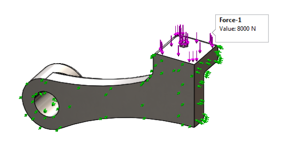
But wait! There’s more! (Erm… less!) This analysis is symmetrical front and
back as well, so we can actually cut it down to a quarter. Like before, we
have to remember to use a reduced load; it’s now a quarter of the full load at
8000 N. And a symmetry restraint needs to be applied to both cut faces.
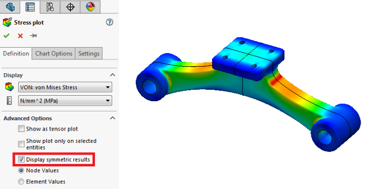
After running the study, the results can be viewed using the same plots and
tools as usual. In addition, we have the option to display symmetric results
and see plots as if we had analyzed the full model.

Again, taking advantage of symmetry is great because it improves efficiency.
This example was quite simple and runs quickly, so I used a fine mesh to help
illustrate the differences between the full, half, and quarter studies. All
three studies produced the same results, but we can see that the quarter study
takes less than a quarter of the time needed to run the full study. And while
10 seconds isn’t a huge amount of time, using symmetry with more complex
studies, which can take minutes or hours to solve, makes a massive difference.
The last thing we should discuss here are situations where symmetry should not
be used. Since symmetry is represented with a restraint to the symmetry plane,
the full model should be use for buckling and frequency studies. Otherwise,
any buckling or vibration modes across the symmetry plane will not be
identified.
I encourage you to use symmetry when you can in your analyses. Check out the next part of this discussion to learn how to handle
non-orthogonal symmetry and symmetry on shell elements in SOLIDWORKS
Simulation.


Terence
Good post – looking forward to special symmetry cases and extreme symmetry. Or have I missed these?
Thanks,
Bill
Hi Bill,
Thanks for reading! It looks like our website team is a bit backlogged at the moment but the other parts should hopefully be up soon. Keep an eye out for them over the next few weeks!
Cheers,
Terence
Can symmetric thermal simulation be visualized? I don’t see any options to apply a symmetric boundary condition. Thus, the option to display full results isn’t available.
Thanks!
Hi Matt,
Unfortunately, that option isn’t available. As you probably already know, for a symmetrical thermal simulation, there is no heat flux across the plane of symmetry. For thermal studies without radiation, we represent this by not applying any thermal conditions to faces on the plane of symmetry so that they behave as insulated faces. Because we do not apply a “symmetry” boundary condition, we do not get the option to “display symmetric results”.
I encourage you to submit an enhancement request through the customer portal. Maybe they can add a symmetry condition for thermal in a future version.
Cheers,
Terence
hello sir. May I have the file bracket? this is my email: [email protected]
I have a few of comments about symmetry to add:
1. In addition to loading and geometry, there should also be symmetry with respect to material properties, although this is more often the case than not if the geometry is symmetric.
2. The real test of symmetry is whether the Results are symmetric. But one may ask how would you know this before solving the problem? Well, the best way to answer this is that for any simulation one should already have a very good idea of what the answer will look like, and the calculated results only provide all the detailed information. Or one should have prior experience that a similar model and setup yields symmetric results. A simple test of a full model with a coarse mesh, and/or 1st-order elements, can also give an idea of the final result.
This is also why it is suggested to avoid using symmetry for frequency and buckling problems; it would ignore the non-symmetric mode shapes that may result. So along the same thread, dynamic problems should follow the same logic as above regarding prior knowledge of the solution.
3. If some of the geometry can be ignored or simplified, without significantly changing the results, so that it becomes symmetric, then this is recommended approach as well. An example that I frequently would use is the screw top of a pressurized bottle; I would eliminate the screw portion, if I am most interested in the stresses at the bottom radius of the bottle, to make the bottle axisymmetric (part of Terence’s extreme symmetry using 2D simplification).
4. I’ve been doing simulations for over 25 years, and even though there is a night-and-day difference with computing hardware from now to back then, using symmetry is still a useful tool as the complexity, detail and accuracy of the problems that we are trying to solve continually increases as well.
How about an antisymmetric relation?