
This is part 2 of a 3 part SOLIDWORKS Simulation Symmetry discussion. Check
out the
first part here
for the basics of using symmetry. In this post, we’re going to look at
applying symmetry to non-orthogonal planes and shell elements.
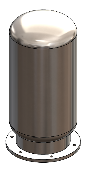 |
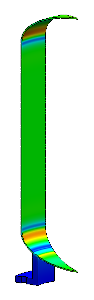
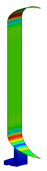
The cylindrical tank above will serve as our example. The model has circular
symmetry with the exception of the 6 holes in the base.
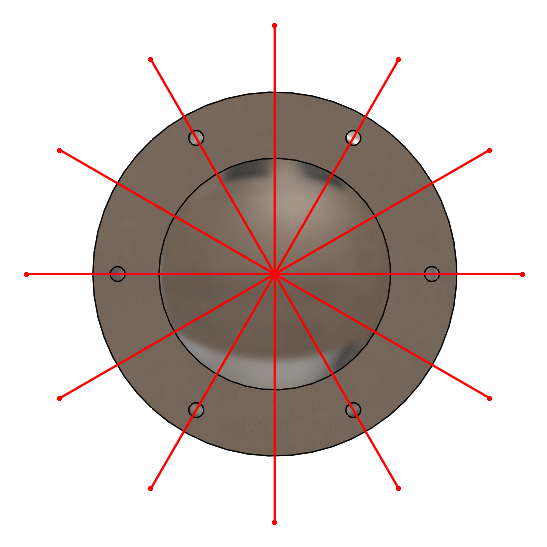 |
Looking at a bottom view, we can see that we have 6 planes of symmetry.
 |
This means that not only can we reduce our tank to a half or quarter model as
we did the first post, we can actually take this model all the way down to a
30-degree slice.
 |
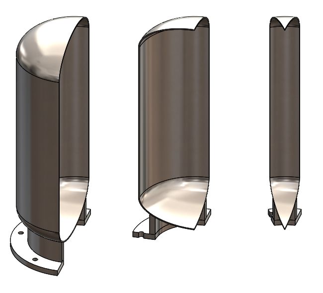
As we discussed in part 1, a symmetry restraint needs to be applied to all of
the symmetry plane faces on both sides of our slice.
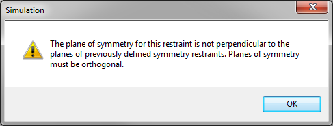 |
However, trying to do so results in a warning. Symmetry fixtures can only be
used when the symmetry planes are perpendicular to each other. This is the
challenge when using non-orthogonal symmetry.
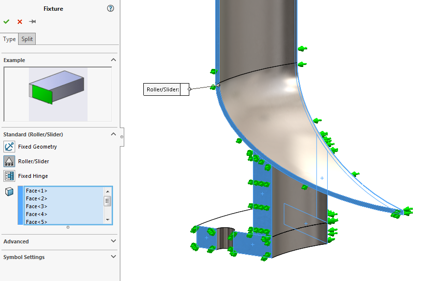 |
Luckily, it’s a very small challenge. Symmetry fixtures simply restrain
out-of-plane displacement and are functionally equivalent to roller/slider
fixtures (for solid mesh). This means we can simply apply a roller/slider
fixture as our symmetry restraint. Challenge overcome!
 |
The only drawback of using roller/slider fixtures instead of symmetry fixtures
is that the option to display symmetric results is not available, but this is
a fairly minor inconvenience.
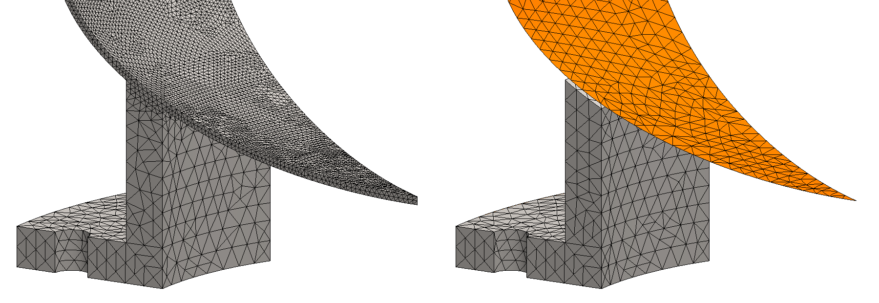 |
This analysis can be performed more efficiently by using shell mesh elements
for the thin walls of the tank. A shell mesh is easy enough to define by using
faces of the solid model or by using a surface model, but a little bit of
extra care is needed if symmetry is involved.
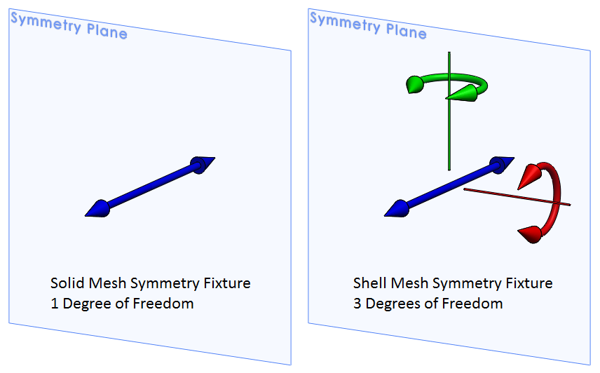 |
The difference between using symmetry on solid mesh or shell mesh comes down
to degrees of freedom (DOF). Mesh nodes of solid elements can translate in 3
DOF only, while mesh nodes of shell elements have 3 translational and 3
rotational DOF. Symmetry fixtures need to restrain all out-of-plane
displacement and for shell elements, this means constraining 2 rotational DOF
in addition to the 1 translation needed for solid elements.
A symmetry fixture recognizes when it is applied to shell mesh and
automatically takes care of all 3 DOF, so most of the time you don’t really
have to worry about it. In cases where symmetry fixtures cannot be applied,
however, it’s important to understand this difference so that symmetry
restraints can be manually defined correctly.
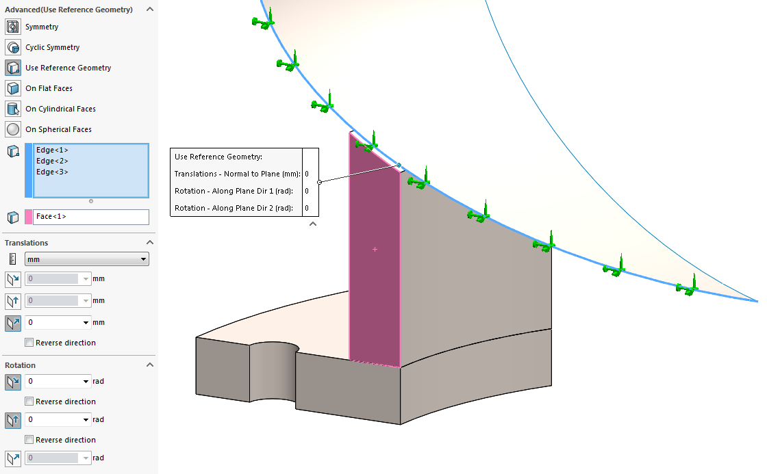 |
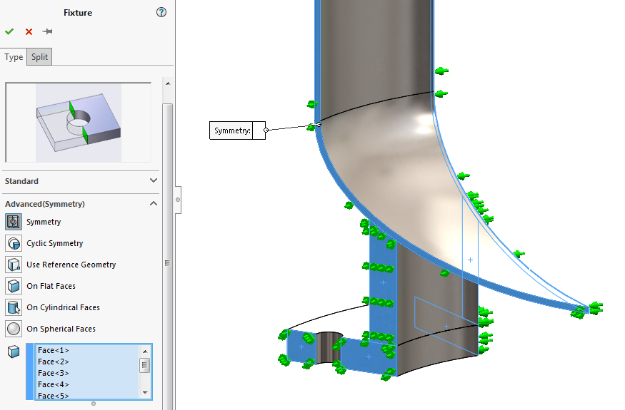
In this example, we can apply an advanced (use reference geometry) fixture to
the edges of the shell on the symmetry plane and use the flat face on the
symmetry plane as the reference. The 1 translation normal to the plane and the
2 rotations about the axes along the plane is set to 0.
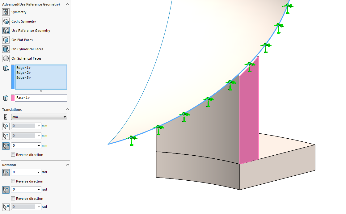 |
A separate fixture needs to be created on the shell for each symmetry plane,
so we need a similar advanced fixture on the other side of the slice.
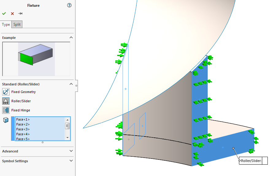 |
Like before, a roller/slider fixture can be used for the solid mesh
components.
 |
And that’s it! Restraining the correct DOF along the symmetry planes is all
that is needed to use symmetry with non-orthogonal planes or shell elements.
To learn how to take this one step further with 2D simplification, check out
part 3 of this discussion
here. For more information, check out our
YouTube channel
or contact us at
Hawk Ridge Systems
today. Thanks for reading!


Out of interest what is the benefit to using the Roller/Slider method instead of the Cyclic Symmetry?
Good question, Scott. A cyclic symmetry fixture actually allows displacement across the planes where it is applied and is intended for situations where you have cyclically repeating tangential loads, so it wouldn’t be the best choice for the example above. I’d recommend checking out the help documentation to learn more: http://help.solidworks.com/2018/english/solidworks/cworks/c_circular_symmetry.htm