Have you ever seen a color 3D printed part and wondered how they do it? Maybe you have tried exporting a file you created with your CAD software only to discover that your part did not carry the color when sent to print.
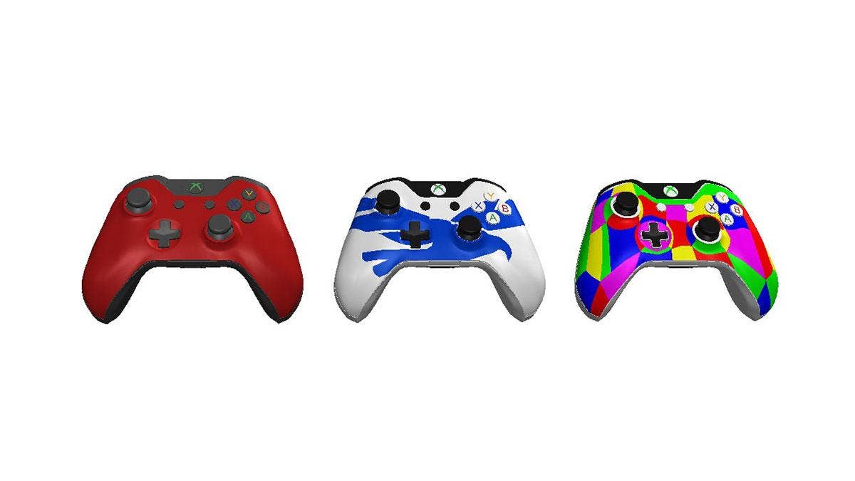
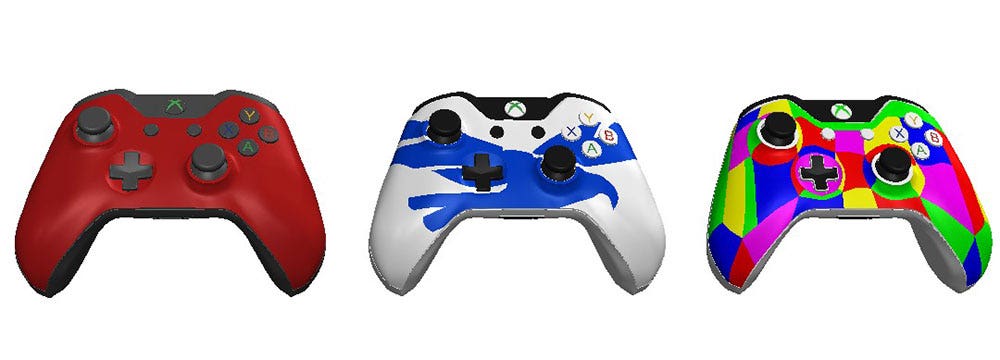 Exporting color data from SOLIDWORKS lets a single controller design print in different color schemes.
I have learned from the school of hard knocks which methods don’t work and which methods will get the job done. In this blog, we are going to look at one of the best methods to export color files for 3D printing. Our CAD program of choice is SOLIDWORKS.
Adding Basic Colors
Starting off, adding a basic color is simple with SOLIDWORKS. By dragging and selecting colors from the Appearance Manager, you have great flexibility in customizing your design. In this example, we will apply the Red High Gloss color from the “Plastics” category.
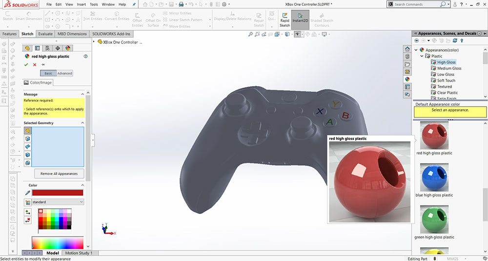 Appearances in SOLIDWORKS can color the complete controller body, as previewed with this red gloss material.
When working with appearances in SOLIDWORKS, you can choose to color the complete part as we have shown below. Alternatively, you can color individual faces, features and surfaces.
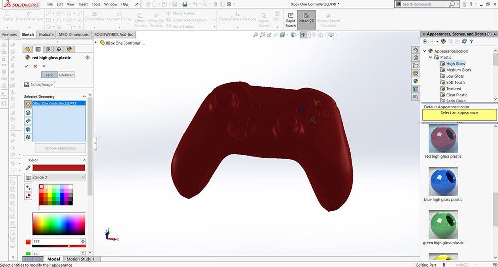 The controller now shows the red gloss appearance applied to its entire body.
For this example, I will only be applying the red gloss appearance to our controller face plate. This is done by selecting each individual surface that I want to color.
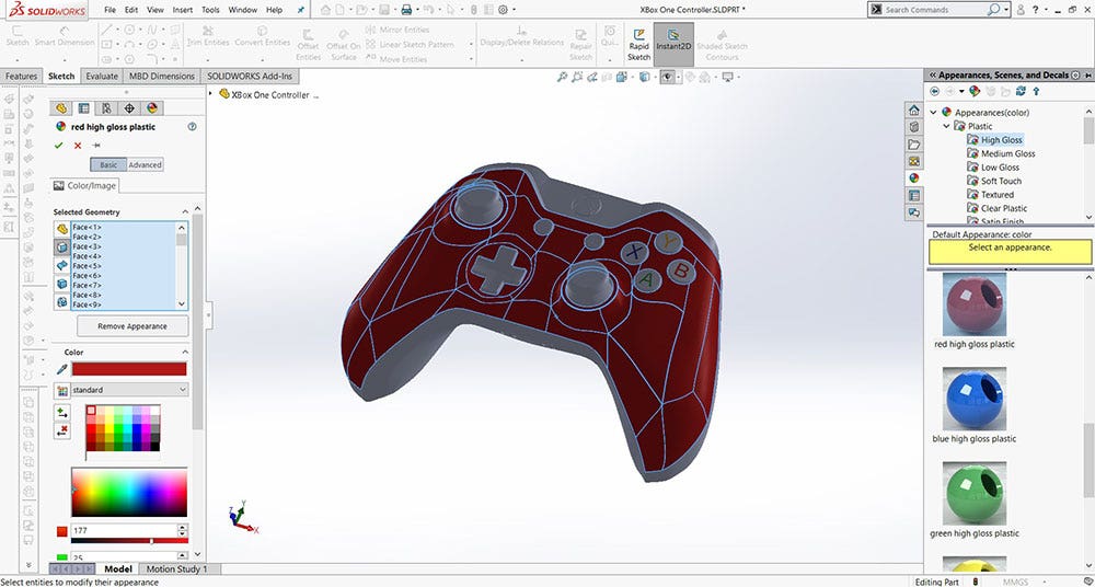 Individual faces, like this selected surface, can be colored separately from the rest of the controller.
I then applied a dark gray appearance to most of the remaining controller surfaces. For contrast, I also decided to color a few of the buttons so that our controller looks like the real deal.
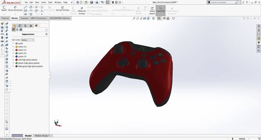 With the coloring complete, the controller model is ready to export as a color-carrying file for printing.
With the coloring of our geometry complete, we can export the model by saving it as a VRML file. This is a file type that carries with it both geometry and color information. Another export option is to save as a 3MF file format, which also can export from SOLIDWORKS with color data. The advantage of the 3MF export is that you can export higher resolution files to reduce tessellation in the final product.
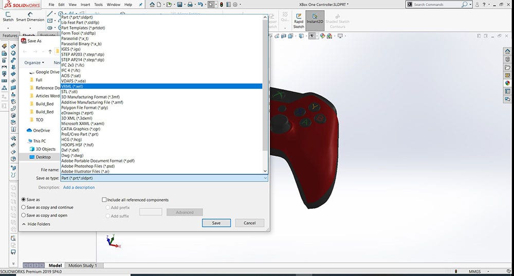 Saving as a VRML or 3MF file carries both geometry and color data needed for 3D color printing.
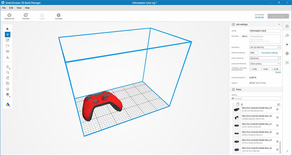 The exported color file loads into the printer’s build manager, positioned within the print volume.
Adding Custom Logos or Graphics
You may have thought that the last section was too easy. How about adding your own custom graphics to a 3D printed part? This is where things can get tricky when exporting for 3D printing. For this section, we’ll focus on adding our Hawk Ridge Systems logo to a part. We’ll start off by using a PNG of the logo, although most image file formats will work for this workflow.
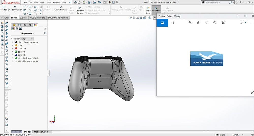 A new rectangular extrusion and PNG logo let the Hawk Ridge Systems graphic be applied to the controller.
Next, we create a new part file and extrude a rectangular sketch. Then, we assign a random color from the Appearance Manager to the extrusion.
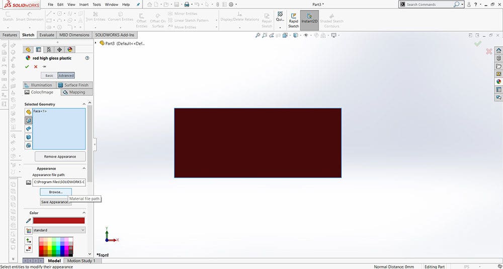 The maroon color appearance is applied first, then the Color/Image tab lets you browse for a logo file.
The next step involves opening the appearance settings for the color we assigned and navigating to the “Advanced” tab. Here, we click on the sub-tab titled “Color/Image.” Then we click “Browse” to find our desired logo image.
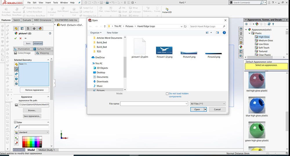 Browsing to a saved logo image file is the first step to mapping custom artwork onto a SOLIDWORKS part.
Note that when you apply an image to a part with this workflow, you will typically need to utilize the “Mapping” tab and orient it correctly on your geometry. I normally use the “Surface” or “Projection” mapping settings to get the logo just right. Another useful option here is “Fit width to selection.”
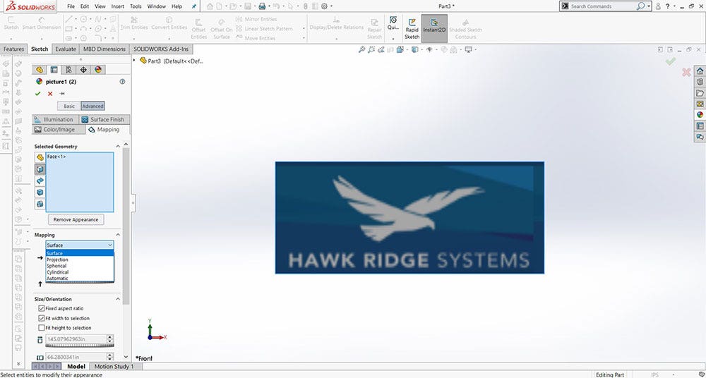 Once loaded, the logo appears in the appearance preview before it is mapped onto the part’s surface.
Now comes the fun part. In this example, I only want the Hawk from the Hawk Ridge Systems logo. To obtain that, I will need to use the spline tool and manually trace the exterior edges of the logo. This took me about 10-15 minutes to do, so take your time and get it right. When tracing your own images, note that this does not have to be one continuous spline; I traced the hawk with several splines that meet at sharp corners to give the best detail. Once you are happy with your logo sketch, go ahead and select the complete sketch by dragging a box around the sketch and then right-click to “copy.” You will want to save this part file to add your logo to future projects!
As a side note, there are more automated ways of completing this step with a bitmap tracer; although automation will sometimes sacrifice sketch quality.
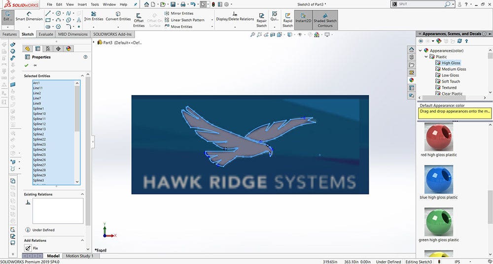 The Appearances panel lists the logo’s mapped entities so its position and scale can be adjusted.
With our hawk sketch copied, we can open up our desired model and start a new sketch on the surface where we would like to apply the logo. To apply the logo, we simply “paste” the copied sketch of the logo into the sketch we just created. Most of the time, the scale and position of your pasted sketch will not be the desired size or scale. If this is the case, the “Move Entities” and “Scale” commands let you set the desired location and scale of your sketch. Sizing issues can potentially be prevented by correctly sizing the initial rectangle that we showed earlier, but I always prefer to scale within my actual part file.
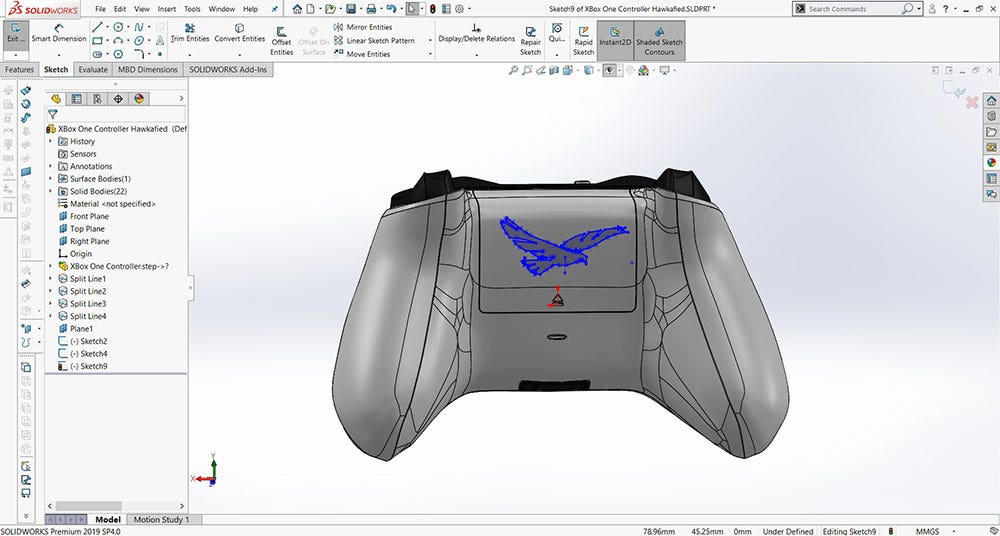 Tracing just the hawk outline with the spline tool isolates the logo shape for placement on the model.
Now that the sketch is placed on our part, we need to turn the sketch into a feature. To do this, we take the sketch and use the “Split Line” command which will project our sketch onto a surface and segment it out without creating physical geometry. To use the “Split Line” command, you would first select your sketch and then the surface that you want to project your sketch onto.
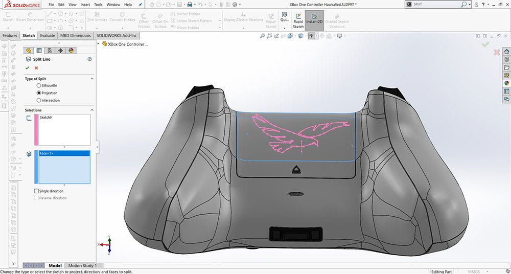 Split Line projects the traced logo sketch onto the surface without adding physical geometry.
Now we have the outline of our logo defined as a sectioned part of the original surface!
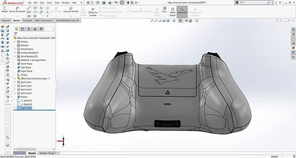 After splitting, the logo outline becomes a defined region of the original surface, ready to color.
Now we can color the logo using the Appearance Manager and save as a VRML or 3MF as we did before!
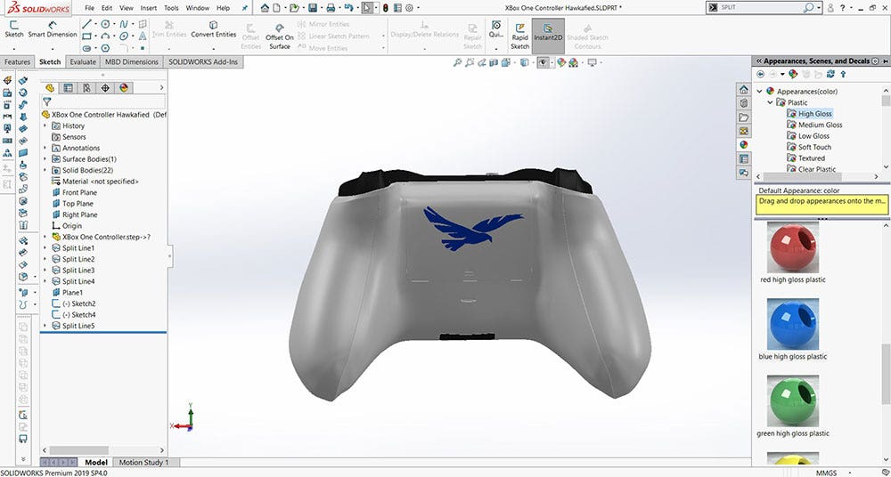 The Appearance Manager colors just the split-off logo region before exporting as VRML or 3MF.
Dealing With Curved Surfaces
We can take this method a step further and project our logo across multiple surfaces that have varying levels of curvature. In this method, you need to define a plane that will act as the platform for your logo. Here we have scaled our Hawk Ridge Logo and positioned it in the middle of the controller. Our plane of choice is facing upward, similar to the “Top View” of our part.
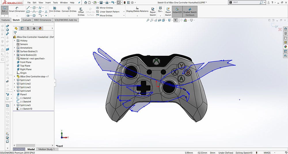 Projecting the logo across a defined plane lets it wrap multiple surfaces with varying curvature.
We then complete the “Split Line” procedure from before and select each surface that we want to show the logo on.
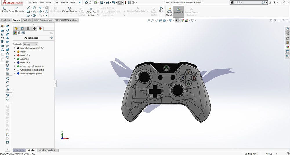 The projected pattern conforms to the controller’s curved housing before the split line step runs.
Next, we color portions of the logo using the Appearance Manager. Our final result is a nice hawk spread out over the curved surfaces of the controller.
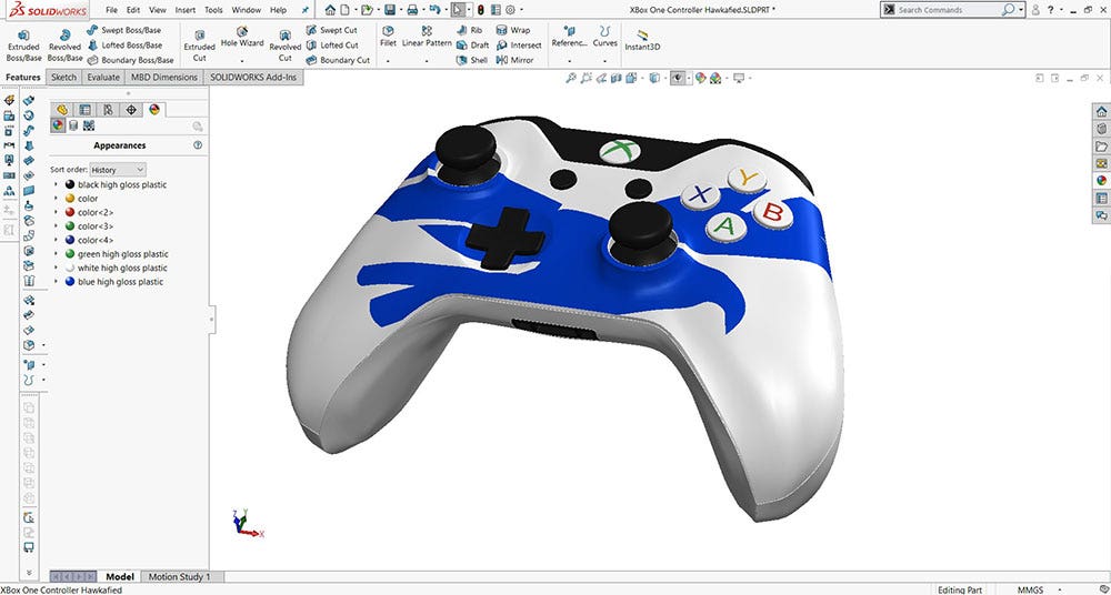 The final render shows the hawk logo spread across the curved surfaces of the controller.
That’s a wrap on the basic tools you need to produce customized color 3D prints with SOLIDWORKS and 3D printers.
If you would like to see how you can start producing your own color parts, contact us at Hawk Ridge Systems today!