Working in the
Hawk Ridge Systems Analysis Services
group, I’ve developed a to-do list before I start any Flow Simulation
analysis. I’ve found that if I do this early, it tends to minimize headaches
when you’ve already put hours and hours into an analysis. The following is a
list of things I do before creating a new
Flow Simulation
study (in no particular order):
Force Rebuild with Verification on Rebuild (VOR) turned on
 turned on")
I tend to do this as soon as I open the file. I go to Tools > Options >
System Options Tab > Performance Section > Verification on Rebuild
checkbox, make sure this is checked, exit out of the options, and press
CTRL-Q. Depending on the file, this may take a while. This setting checks
every feature against all existing faces and edges, not just adjacent faces
and edges. When this option is turned on, features that cause invalid geometry
fail. If any features fail, fix them now.
Check Entity

This is a really simple tool for checking for invalid faces and edges. This
tool is especially helpful when you have imported geometry. This tool can be
found at the part or assembly level under Tools > Check.
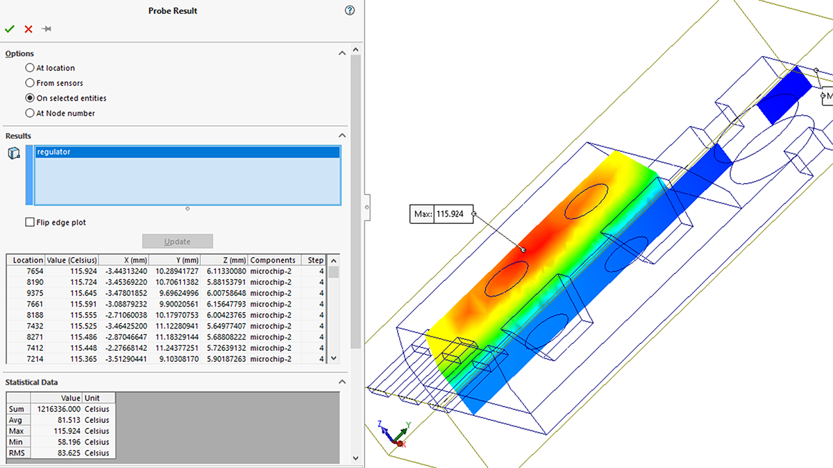
Flow Simulation’s Check Geometry

This is a great way to find out if you have any invalid contacts that Flow
Simulation doesn’t like. Certain invalid contacts can be fixed by this tool,
but it is a good idea to fix these yourself before proceeding any further.
This tool will also check if you have a fully enclosed fluid volume, something
you are going to need if you are doing an internal analysis. This tool can be
found with the Flow Simulation add-in turned on under Flow Simulation >
Tools > Check Geometry.
Interference Detection

 Interference detection is a very useful tool for Simulation as well as Flow
Simulation. Flow Simulation is not as concerned with interference, but if you
are doing heat conduction problems it is found in your Evaluate tab on the
Command Manager, or under Tools > Interference Detection (at the Assembly
level). very important that the faces that you think are touching, are
actually touching. This is where the “Treat coincidence as interference”
checkbox comes in. Having this checkbox on will list, in addition to any
material interferences, all sets of touching faces. Also, a checkbox that
should be on is the “Include multibody part interferences” (don’t want to
forget those). This tool can be found in your Evaluate tab on the Command
Manager, or under Tools > Interference Detection (at the Assembly level).
Bonus: Import Diagnostics
If you use imported geometry (IGES, STEP, Parasolid, etc.), this tool is
something you should already be familiar with. There are many times where I
have seen customers import their geometry, start adding features, and then
when they start to have problems, we find that their initial geometry was
faulty. This ends up costing the customer a lot of time remaking their part;
simply running the diagnostic tool in the beginning would have saved a lot
of headaches. If this finds any faulty faces or gaps, you can try to heal
all; if this doesn’t fix it you may have to start deleting and patching
faces manually. This tool can be found at the part level, under Tools >
Import Diagnostics.
Hopefully this checklist will help you catch potential problems before they
turn into nightmares. Good luck and happy Simulating!

hi.i need help to analysis a fan rotation when i do it out let of air in my test relate on one axis but i don’t want shown in one axis help me please with pictures.thanks
Tamsa,
You can contact me directly at [email protected] and we can talk more about your question. Thanks for reading!
Thank you very much for a good tip list!
Hi , I think I’ve a problem running a simulation on a drone blade, I’ve run tests before with different model and was able to obtain results.
I’ve designed my own blades and I’ve got my surface goals for force, rotating region set, fluid domain set. The problem occurs when i run the simulation it stays at ‘Preparing Model’ and doesn’t begin the calculations… I’ve done the steps you showed above.
Any help appreciated
Dallan
Dallan.
A couple of things to look at – try setting the mesh resolution to a really low level – it might be getting hung up on preparing to mesh.
In the Flow Simulation check geometry tool, make sure the fluid volume looks like the area you’re planning to analyze – it could be picking up the wrong volume.
Through Task Manager, check your computer’s resources as you launch the solve. If you’re pegging out your memory, you may need to simplify the mesh or the model.
And a last potential one, on your first analysis on a new computer the solver process (efdsolver.exe) can often throw up a Windows error asking for permission to execute. Make sure that message hasn’t popped up in the background
If none of that works, the sure-fire way to solve this is to simplify your model to the point where it works. Delete all but one part in the model, set up a basic analysis, and see if you can get it to launch the solver and mesh. Then, incrementally add things back, re-running as you add each set of few parts. When it stops working, you’ve found your problem part.
If it’s a single part, use a cut command to cut away most of the model and try the same process.
Glenn,
How do you lower the mesh resolution for the entire model?
Thanks,
Clint
Thanks for informing me that the “check geometry” tool is a great way to know if there’s any invalid contact that would hinder the flow simulation from working efficiently. This would be a good tip for me because we’re planning to get a process engineering software at work for fluid flow simulation. I’ll bookmark this article so I can check on it if I encounter any issues with any flow simulation analysis at work.
I have the same problem that Bran exposes above and I cannot make him finish the calculations, he does not even start them … He gets stuck in “Preparing model” I already made more than 10 different models with different levels of complexity and the same thing happens. It is possible that the firewall is blocking this process (efdsolver.exe) in that case, how do I unblock it? From already thank you very much!
Hi Eloy,
If this is happening on all Flow simulations you try (test with a tutorial file like the ball valve and watch the task manager for the efdsolver.exe process) I would suggest adjusting your UAC level down and add the efdsolver.exe to the allow list in your firewall settings to see if that has any effect. This could also be related to a virus scanning tool or the install. You can repair the installation by going to the programs and features area, selecting SOLIDWORKS and clicking change, finally use the Repair option to complete the process.
Hi Clint,
In general, if you go to the mesh entry in the tree, right-click and pick “global mesh” you can make overall mesh adjustments. If you’re set to the automatic, move the slider to the left. If you’re set to manual, make the numbers for the number of elements per direction smaller.
Either should scale the overall mesh count down in the model while retaining all your other mesh customizations and refinements.